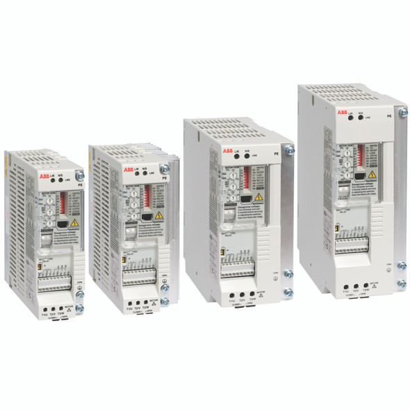
Description
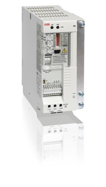
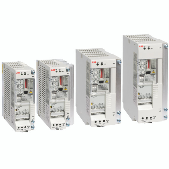
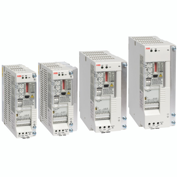
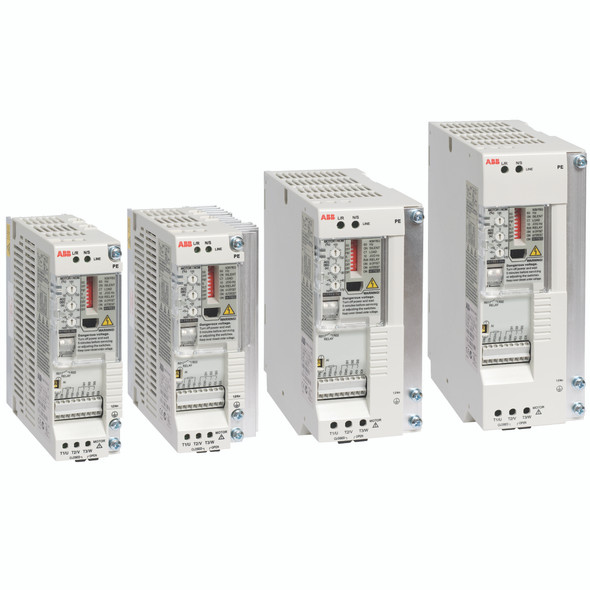
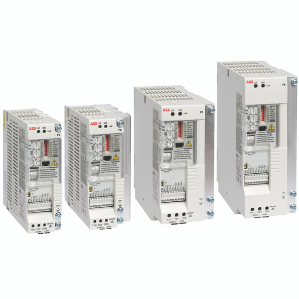
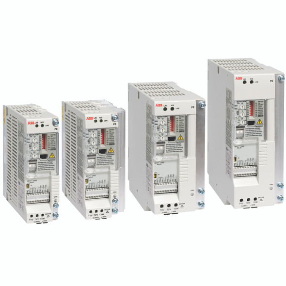
Ensure speed and control features in a variety of your low power applications such as automatic gate, solar trackers, treadmills and whirlpool baths. So easy to set up and commission, the design focus of the ACS55 is on easy integration into machines, with flexible mounting alternatives. The DriveConfig kit option allows set up without a power connection to the drive. It’s also ready to go for commercial and domestic environments.
Highlights
- Power range 0.18 to 2.2 kW/0.25 to 3 Hp
- IP20 enclosure (UL open)
- Scalar control
- For basic machinery applications
- Suitable for domestic networks as standard
- Parameter setting by switches or by PC software
- Built-in EMC filter for 1st environment
ABB ACS55 Micro Drives Catalog
ABB ACS55 DriveConfig Manual - DriveConfig PC tool is a parameterising and maintenance tool for the ACS55 drive series.
How to Configure and Order ABB ACS55 Micro Drives: Refer to the Type Designation Column in this Chart
See all ACS55 Configurations and Options Here - Online Purchase Available
| 0.25 - 0.5HP (1~110 - 120V In/ 3~240V Out) 0.25 - 3 HP (3~200-240V In/3~240 Out) | ||
| Input ratings | Input voltage range | 1-phase, 110 - 120V 1-phase, 200 - 240V |
| Input voltage tolerance | 10%/-15% | |
| Phase | Single phase | |
| Frequency | 48 to 63Hz, maximum rate of change = 17% / sec | |
| Short circuit rating (UL 508c) | 100,000 rms symmetrical amperage up to 600 V when input cables protected by class T fuses or similar type fuse. | |
| Output ratings | Horsepower | 0.25 - 0.5 HP @ 120 VAC, 3PH 0.25 - 3 HP @ 240 VAC, 3PH |
| Overload capacity | Drive Output 150% for 1 min., 180% for 2 sec. at start | |
| Frequency | 0-130 Hz | |
| Voltage | 0 to maximum input voltage RMS | |
| Motor types | Asynchronous AC induction motors | |
| Protective features | Overcurrent | Excessive output current |
| DC bus overvoltage | High DC bus | |
| Overtemp | Heatsink Monitor (90°C / 203°F) | |
| Short circuit | Short on motor terminals | |
| DC Undervoltage | Low voltage on drive input | |
| Loss of reference | Analog input programmed for 4-20ma but signal less than 4ma | |
| Motor overtemp | Excessive estimated motor temperature | |
| Ground fault | Ground fault detected in motor or motor cabling | |
| Environmental | Temperature | -20 to 40 C (-4 to 104 F), no frost allowed, 50 C (122 F) with 15% derate, 55 C (131 C)with 25% derate |
| Cooling | Natural convection | |
| Enclosure | UL Open (IP20) | |
| Altitude | Sea level to 3300 ft. (1000 m), derate 1% per 330 ft. (100 m) up to 6600 ft. (2000 m) | |
| Humidity | 0 to 95% RH non-condensing | |
| Vibration | In accordance with ISTA 1A | |
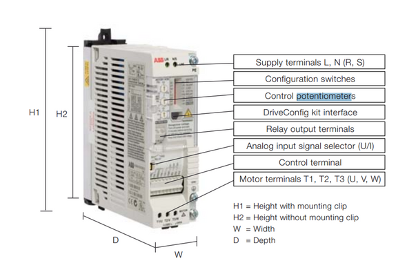
| Keypad display | Display | Control potentiometers and dip switches |
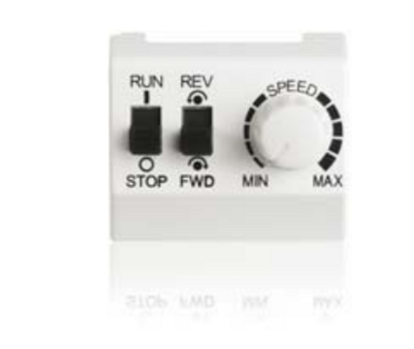
| Functions | Optional speed potentiometer and control switches | |
| Trip | Green and red status indication LED's | |
| Control specifications | Switching frequency | 5 (default) to 16 kHz |
| Accel/decel | 0 to 100 s | |
| Skip frequencies | 0 | |
| PC setup software | DriveConfig | |
| Maximum output frequency | 250 Hz | |
| Selectable operating modes | 2-wire, 3-wire, Motor potentiometer, Constant speed | |
| Analog inputs | Two selectable current or voltage | 0-10VDC, -10 to 10VDC or 0/4 - 20maDC |
| Resolution | 0.1% | |
| Digital inputs | Three (3) digital inputs | 12 to 24VDC, (10V Logic 0) with internal 12 VDC power supply (12 VDC, +/-10%, 30mA max.) |
| Input impedance | Pull-up (PNP) | |
| Filtering | Update time 2 ms | |
| Digital outputs | One relay output | Form C, 250 VAC/30 VDC, 2 A rms |

